How Circuits Work

The circuit illustration above shows how the circuit of a flashlight works.
2007 HowStuffWorks

Have you ever wondered what happens when you flip a switch to turn on a light[, TV, vacuum cleaner or computer? What does flipping that switch accomplish? In all of these cases, you are completing an electric circuit, allowing a current, or flow of electrons, through the wires.

An electric circuit is in many ways similar to your circulatory system. Your blood vessels, arteries, veins and capillaries are like the wires in a circuit. The blood vessels carry the flow of blood through your body. The wires in a circuit carry the electric current to various parts of an electrical or electronic system.

Advertisement

Your heart is the pump that drives the blood circulation in the body. It provides the force or pressure for blood to circulate. The blood circulating through the body supplies various organs, like your muscles, brain and digestive system. A battery or generator produces voltage -- the force that drives current through the circuit.

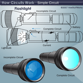
Take the simple case of an electric light. Two wires connect to the light. For electrons to do their job in producing light, there must be a complete circuit so they can flow through the light bulb and then back out.

The diagram above shows a simple circuit of a flashlight with a battery at one end and a flashlight bulb at the other end. When the switch is off, a complete circuit will not exist, and there will be no current. When the switch is on, there will be a complete circuit and a flow of current resulting in the flashbulb emitting light.

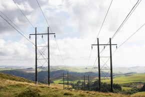
Circuits can be huge power systems transmitting megawatts of power over a thousand miles -- or tiny microelectronic chips containing millions of transistors. This extraordinary shrinkage of electronic circuits made desktop computers possible. The new frontier promises to be nanoelectronic circuits with device sizes in the nanometers (one-billionth of a meter).

In this article, we'll learn about the two basic types of electric circuits:

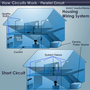
  • Power circuits transfer and control large amounts of electricity. Examples are power lines and residential and business wiring systems. The major components of power circuits are generators at one end and lighting systems, heating systems or household appliances at the other end. In between are power lines, transformers and circuit breakers.
  • Electronic circuits process and transmit information. Think computers, ­ ­radios, TVs, radars and cell phones.

Circuit Basics

This circuit board contains many individual circuits.
Guy Crittenden/Digital Vision/Getty Images

You've probably heard these terms before. You knew they had something to do with electricity, but maybe you weren't sure quite sure how.

Just as your heart produces the pressure to make blood circulate, a battery or generator produces the pressure or force to push electrons around a circuit. Voltage is the force and is measured in volts (V). A typical flashlight battery produces 1.5V, and the standard household electrical voltage is 110V or 220V.

Advertisement

­Electrical current, or flow of electrons, is measured in amperes (A). The product of electric force (in volts) and current (in amperes) is electrical power, measured in watts (W). A battery generating 1.5V and producing a current flow of 1A through a flashlight bulb delivers 1.5V x 1A = 1.5W of electrical power.

The blood flowing through your body doesn't get a free ride. The walls of the blood vessels impede the flow, and the smaller the blood vessel, the more the resistance to flow. Some of the pressure produced by your heart is just for pushing blood through blood vessels. As electrons move through wires, they bump into atoms. This impedes the flow of the electrons. The wire offers resistance to the flow of the current. The amount of resistance depends on the material, diameter and length of the wire. The resistance increases as the diameter of the wire decreases. Resistance is in units of ohms (Ω).

Ohm's Law relates voltage, current and resistance:

Resistance (Ω) = Voltage (V)/ Current (I)

Ohm's Law can be written as R = V/I.

Electric circuits are composed of wires and other components -- like light bulbs, transistors, computer chips and motors. Wires, made of metals called conductors that have a low resistance to current, connect the components. Copper and aluminum are the most common conductors. Gold, because of its resistance to corrosion, is often used for attaching wires to tiny electronic chips.

­In an incandescent bulb, the current flows through a thin tungsten wire or a metallic filament that offers high resistance to current flow. When the electrons bump into the atoms, the friction, or loss of kinetic energy, produces heat. If the temperature of the filament is high enough, it starts to glow and give off light. This is incandescence. Typical filament temperatures for light bulbs are around 4,600 degrees F (2,550 degrees C). Unfortunately, 90 to 95 percent of the energy supplied to a light bulb is lost in the form of heat rather than light, so incandescent bulbs are very inefficient.­

Fluorescent lights produce light by having electrons pass through a tube filled with mercury vapor and neon or argon gas. As the electrons bump into the mercury atoms, they cause electrons in the atoms to absorb some of their energy. As these electrons return to their normal state, they radiate bundles of light energy called photons. Fluorescent lights are four to five times more efficient than incandescent bulbs.

On the next page, we'll look at closed circuits, open circuits, short circuits, series circuits and parallel circuits.

Types of Circuits

Parallel Circuits Illustration
2008 HowStuffWorks

A closed circuit has a complete path for current to flow. An open circuit doesn't, which means that it's not functional. If this is your first exposure to circuits, you might think that when a circuit is open, it's like an open door or gate that current can flow through. And when it's closed, it's like a shut door that current can't flow through. Actually, it's just the opposite, so it might take awhile to get used to this concept. 

A short circuit is a low-resistance path, usually made unintentionally, that bypasses part of a circuit. This can happen when two bare wires in a circuit touch each other. The part of the circuit bypassed by the short circuit ceases to function, and a large amount of current could start to flow. This can generate a lot of heat in the wires and cause a fire. As a safety measure, fuses and circuit breakers automatically open the circuit when there is an excessive current.

Advertisement

In a series circuit, the same current flows through all the components. The total voltage across the circuit is the sum of the voltages across each component, and the total resistance is the sum of the resistances of each component. In this circuit, V = V1 + V2 + V3 and R = R1 + R2 + R3. An example of a series circuit is a string of Christmas lights. If any one of the bulbs is missing or burned out, no current will flow and none of the lights will go on.

Parallel circuits are like the smaller blood vessels that branch off from an artery and then connect to a vein to return blood to the heart. Now think of two wires, each representing an artery and a vein, with some smaller wires connected between them. These smaller wires will have the same voltage applied to them, but different amounts of current flowing through them depending on the resistance of the individual wires.

An example of a parallel circuit is the wiring system of a house. A single electric power source supplies all the lights and appliances with the same voltage. If one of the lights burns out, current can still flow through the rest of the lights and appliances. However, if there is a short circuit, the voltage drops to almost zero, and the entire system goes down.

Circuits are generally very complex combinations of series and parallel circuits. The first circuits were very simple DC circuits. We'll look at the history of circuits and the difference between DC and AC on the next page.­

History of Electrical Circuits

Japanese Prime Minister Junichiro Koizumi laughs as a balloon clings to him with a static electrical charge. ­
Junko Kimura/Getty Images

Early investigations of static electricity go back hundreds of years. Static electricity is a transfer of electrons produced by friction, like when you rub a balloon across a sweater. A spark or very brief flow of current can occur when charged objects come into contact, but there is no continuous flow of current. In the absence of a continuous current, there is no useful application of electricity.

The invention of the battery -- which could produce a continuous flow of current -- made possible the development of the first electric circuits. Alessandro Volta invented the first battery, the voltaic pile, in 1800. The very first circuits used a battery and electrodes immersed in a container of water. The flow of current through the water produced hydrogen and oxygen.

Advertisement

The first widespread application of electric circuits for practical use was for electric lighting. Shortly after Thomas Edison invented his incandescent light bulb, he sought practical applications for it by developing an entire power generation and distribution system. The first such system in the United States was the Pearl Street Station in downtown Manhattan. It provided a few square blocks of the city with electric power, primarily for illumination.

One classification of circuits has to do with the nature of the current flow. The earliest circuits were battery-powered, which made in a steady, constant current that always flowed in the same direction. This is direct current, or DC. The use of DC continued through the time of the first electric power systems. A major problem with the DC system was that power stations could serve an area of only about a square mile because of power loss in the wires.

In 1883, engineers proposed harnessing the tremendous hydroelectric power potential of Niagara Falls to supply the needs of Buffalo, N.Y. Although this power would ultimately go beyond Buffalo to New York City and even farther, there was an initial problem with distance. Buffalo was only 16 miles from Niagara Falls, but the idea was unworkable -- until Nikola Tesla made it possible, as we'll see on the next page.

Tesla's Breakthrough

Before the discovery of AC, or alternating current, power, long-distance power transmission wasn't possible.­
Tim Robberts/Photographers Choice/Getty Images

Engineer Nikola Tesla, aided by theoretical work by Charles Proteus Steinmetz, came up with the idea of using alternating current, or AC. Unlike direct current, AC is always changing and repeatedly reverses direction.

So why was AC the answer to the problem of long-distance power transmission? With AC, it's possible to use transformers to change voltage levels in a circuit. Transformers work on a principle of magnetic induction, which requires a changing magnetic field produced by the alternating current. With transformers, voltages can be increased for long-distance transmission. At the receiving end, the voltage level can decrease to a safer 220V or 110V for business and residential use.

Advertisement

We need high voltages for long distances because wire resistance causes power loss. The electrons bumping into atoms lose energy in the form of heat as they travel. This power loss is proportional to the square of the amount of current moving through the wire.

To measure the amount of power the line transmits, you can multiply the voltage by the current. You can express these two ideas using an equation in which I represents current, V represents voltage and P equals power:

P = V x I

Let's consider the example of transmitting 1 megawatt. If we increase the voltage from 100V to 10,000V, we can then decrease the current from 10,000A to 100A. This will reduce the power loss by (100)2, or 10,000. This was Tesla's concept, and from that idea power transmission from Niagara Falls to Buffalo, and ultimately to New York City and beyond, became a reality.

 In the United States and many other countries, the standard frequency for AC power is 60 cycles per second, or 60 hertz. This means that 60 times a second, a complete cycle of the current flows in one direction and then in the other. The current flows in one direction for 1/120th of a second and in the other direction for another 1/120th of a second. The time it takes for one cycle to be completed is called a period, which in this case is 1/60th of a second. In Europe and other areas, the standard frequency for AC power is 50 hertz.

Electronic circuits need both AC and DC. We'll learn about them on the next page.

Electronic Circuits

You may have heard the term chip, especially when the subject of computer hardware comes up. A chip is a tiny piece of silicon, usually around one centimeter square. A chip may be a single transistor (a piece of silicon that amplifies electrical signals or serves as an on/off switch in computer applications). It can also be an integrated circuit composed of many interconnected transistors. Chips are encapsulated in a hermetically sealed plastic or ceramic enclosure called a package. Sometimes people refer to the whole package as a chip, but the chip is actually inside the package.

There are two basic types of integrated circuit -- monolithic and hybrid. Monolithic ICs include the entire circuit on a single silicon chip. They can range in complexity from just a few transistors to millions of transistors on a computer microprocessor chip. A hybrid IC has a circuit with several chips enclosed in a single package. The chips in a hybrid IC may be a combination of transistors, resistors, capacitors and monolithic IC chips.

Advertisement

A printed circuit board, or PCB, holds an electronic circuit together. The completed PCB with components attached is a printed circuit board assembly, or PCBA. A multilayer PCB may have as many as 10 stacked PCBs. Electroplated copper conductors passing through holes called vias connect the individual PCBs, which forms a three-dimensional electronic circuit.

The most important elements in an electronic circuit are the transistors. Diodes are tiny chips of silicon that act as valves to allow current flow in only one direction. Other electronic components are passive elements like resistors and capacitors. Resistors offer a specified amount of resistance to current, and capacitors store electric charge. The third basic passive circuit element is the inductor, which stores energy in the form of a magnetic field. Microelectronic circuits very rarely use inductors, but they are common in larger power circuits.

Most circuits are designed using computer-aided design programs, or CAD. Many of the circuits used in digital computers are extremely complex and use millions of transistors, so CADs are the only practical way to design them. The circuit designer starts with a general specification for the functioning of the circuit, and the CAD program lays out the complex pattern of interconnections.

The etching of the metal interconnection pattern on a PCB or IC chip uses an etch-resistant masking layer to define the circuit pattern. The exposed metal is etched away, leaving the pattern of connecting metal between components.

Why is AC used in electronic circuits?

In electronic circuits, the distances and currents are very small, so why use AC? First of all, the currents and voltages in these circuits represent constantly changing phenomena, so the electrical representations, or analogs, are also constantly changing. The second reason is that radio waves (like those used by TVs, microwaves and cell phones) are high-frequency AC signals. The frequencies used for all types of wireless communication has steady advanced over the years, from the kilohertz (kHz) range in the early days of radio to the megahertz (MHz) and gigahertz (GHz) range today.

Electronic circuits use DC to provide power for the transistors and other components in electronic systems. A rectifier circuit converts AC power to DC from the AC line voltage.

Lots More Information

Related HowStuffWorks Articles

More Great Links

  • All About Circuits. http://www.allaboutcircuits.com/
  • Lessons in Electric Circuits. http://www.ibiblio.org/obp/electricCircuits/
  • Electric Circuit Concepts. http://hyperphysics.phy-astr.gsu.edu/Hbase/electric/ecircon.html
  • Lessons in Electric Circuits. http://www.electriccircuits.net/

­