Space Shuttle Improvements
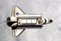
As mentioned previously, falling debris (foam insulation) from the ET damaged the shuttle orbiter, leading to Columbia's break up upon re-entry. To bring the shuttles back to flight status, NASA has focused on three major areas:
- Redesign the ET to prevent insulation from damaging the shuttle orbiter
- Improve inspection of the shuttle to detect damage
- Find ways to repair possible damage to the orbiter while in orbit
- Formulate contingency plans for the crew of a damaged shuttle to stay at the ISS until rescue
Let's take a closer look at each of these.
Advertisement
ET Redesign
The ET holds cold liquefied gases as fuel (oxygen, hydrogen). Because the temperatures are so cold, water from the atmosphere condenses and freezes on the surfaces of the ET and the fuel lines leading in to the orbiter. Ice can fall off the ET itself or cause the ET foam insulation to crack and fall off. In addition to ice, if any of the liquid gas were to leak and get under the foam, it would expand and cause the foam insulation to crack. So much of the ET redesign has focused on eliminating places where condensation can occur.
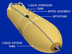
First, the bipod fitting is the forward point where the ET attaches to the underside of the orbiter. Engineers and technicians discovered that this point is especially susceptible to icing. In the past, ramps of foam insulation over this part prevented ice buildup; however, this insulation fell off frequently, thereby presenting a danger to the orbiter.
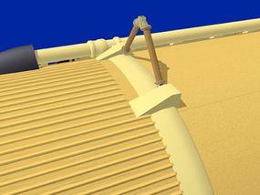
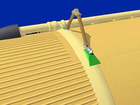
In the redesign, the insulation has been removed and the fitting now mounts across the top of a copper plate, which contains electric heaters. The heater can warm the fitting and prevent ice buildup.
Second, liquid nitrogen is used to purge the intertank connection of any potentially explosive hydrogen gas. However, liquid nitrogen can freeze around the bolts in that area and cause foam insulation to break off. The bolts in that area have been redesigned to prevent leaks of liquid nitrogen.
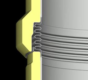
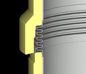
Third, five liquid oxygen feedline bellows lie along the umbilicus that connects the liquid oxygen tank with the main engines and are attached to the liquid hydrogen tank. The bellows compensate for expansions and contractions that occur when the liquid hydrogen tank is filled and emptied. The bellows prevent stresses on the feedline. Previously, the foam insulation overlying the bellows was angled. This angle allowed water vapor to condense, run between the foam insulation, and freeze, thereby breaking the foam. To correct this problem, the foam skirt of this joint has been extended over the insulation below and squared off so that water cannot run between the foam.