How Tunnels Work

Up Next

­At its most basic, a tunnel is a tube hollowed through soil or stone. Constructing a tunnel, however, is one of the most compl­ex challenges in the field of civil engineering. Many tunnels are considered technological masterpieces and governments have honored tunnel engineers as heroes. That's not to say, of course, that some tunnel projects haven't encountered major setbacks. The Central Artery/Tunnel Project (the "Big Dig") in Boston, Massachusetts was plagued by massive cost overruns, allegations of corruption, and a partial ceiling collapse that resulted in a fatality. But these challenges haven't stopped engineers from dreaming up even bigger and bolder ideas, such as building a Transatlantic Tunnel to connect New York with London.

In this article, we'll explore what makes tunnels such an attractive solution for railways, roadways, public utilities and telecommunications. We'll look at the defining characteristics of tunnels and examine how tunnels are built. We'll also look at the "Big Dig" in detail to understand the opportunities and challenges inherent to building a tunnel. Finally, we'll look at the future of tunnels.

Tunnel Image Gallery

Gotthard Base Tunnel
Image courtesy Daniel Schwen/
used under Creative Commons Attribution-ShareAlike License
The Gottha­rd Base Tunnel, a railway tunnel under construction in Switzerland. See more pictures of tunnels.

Tunnel Basics
A tunnel is a horizontal passageway located underground. While erosion and other forces of nature can form tunnels, in this article we'll talk about man made tunnels -- tunnels created by the process of excavation. There are many different ways to excavate a tunnel, including manual labor, explosives, rapid heating and cooling, tunneling machinery or a combination of these methods.

Some structures may require excavation similar to tunnel excavation, but are not actually tunnels. Shafts, for example, are often hand-dug or dug with boring equipment. But unlike tunnels, shafts are vertical and shorter. Often, shafts are built either as part of a tunnel project to analyze the rock or soil, or in tunnel construction to provide headings, or locations, from which a tunnel can be excavated.

The diagram below shows the relationship between these underground structures in a typical mountain tunnel. The opening of the tunnel is a portal. The "roof" of the tunnel, or the top half of the tube, is the crown. The bottom half is the invert. The basic geometry of the tunnel is a continuous arch. Because tunnels must withstand tremendous pressure from all sides, the arch is an ideal shape. In the case of a tunnel, the arch simply goes all the way around.

A basic tunnel

Tunnel engineers, like bridge engineers, must be concerned with an area of physics known as statics. Statics describes how the following forces interact to produce equilibrium on structures such as tunnels and bridges:

  • Tension, which expands, or pulls on, material
  • Compression, which shortens, or squeezes material
  • Shearing, which causes parts of a material to slide past one another in opposite directions
  • Torsion, which twists a material
The tunnel must oppose these forces with strong materials, such as masonry, steel, iron and concrete.

Forces acting on tunnel

In order to remain static, tunnels must be able to withstand the loads placed on them. Dead load refers to the weight of the structure itself, while live load refers to the weight of the vehicles and people that move through the tunnel.

We'll look at the basic types of tunnels next.

Advertisement

Types of Tunnels

There are three broad categories of tunnels: mining, public works and transportation. Let's look briefly at each type.

Mine tunnels are used during ore extraction, enabling laborers or equipment to access mineral and metal deposits deep inside the earth. These tunnels are made using similar techniques as other types of tunnels, but they cost less to build. Mine tunnels are not as safe as tunnels designed for permanent occupation, however.

A coal miner standing on the back of a car in a mine tunnel
  Photo courtesy National Photo Company Collection/Library of Congress Prints and Photographs Division
A coal miner standing on the back of a car in a mine tunnel in the early 1900s. Notice that the sides of the tunnel are shored up with timber.


Public works tunnels carry water, sewage or gas lines across great distances. The earliest tunnels were used to transport water to, and sewage away from, heavily populated regions. Roman engineers used an extensive network of tunnels to help carry water from mountain springs to cities and villages. These tunnels were part of aqueduct systems, which also comprised underground chambers and sloping bridge-like structures supported by a series of arches. By A.D. 97, nine aqueducts carried approximately 85 million gallons of water a day from mountain springs to the city of Rome.

 Roman aqueduct from Pools of Solomon to Jerusalem
  Photo courtesy Eric and Edith Matson Photograph Collection/Library of Congress Prints and Photographs Division
A Roman aqueduct that runs from the Pools of Solomon
to Jerusalem


Before there were trains and cars, there were transportation tunnels such as canals -- artificial waterways used for travel, shipping or irrigation. Just like railways and roadways today, canals usually ran above ground, but many required tunnels to pass efficiently through an obstacle, such as a mountain. Canal construction inspired some of the world's earliest tunnels.

The Underground Canal, located in Lancashire County and Manchester, England, was constructed from the mid- to late-1700s and includes miles of tunnels to house the underground canals. One of America's first tunnels was the Paw Paw Tunnel, built in West Virginia between 1836 and 1850 as part of the Chesapeake and Ohio Canal. Although the canal no longer runs through the Paw Paw, at 3,118 feet long it is still one of the longest canal tunnels in the United States.

Holland tunnel
Photo courtesy Kmf164/ Creation Commons Attribution Share-alike License
Traveling through the Holland Tunnel from Manhattan to New Jersey


­ By the 20th century, trains and cars had replaced canals as the primary form of transportation, leading to the construction of bigger, longer tunnels. The Holland Tunnel, completed in 1927, was one of the first roadway tunnels and is still one of the world's greatest engineering projects. Named for the engineer who oversaw construction, the tunnel ushers nearly 100,000 vehicles daily between New York City and New Jersey.

Tunnel construction takes a lot of planning. We'll explore why in the next section.

Advertisement

Tunnel Planning

Almost every tunnel is a solution to a specific challenge or problem. In many cases, that challenge is an obstacle that a roadway or railway must bypass. They might be bodies of water, mountains or other transportation routes. Even cities, with little open space available for new construction, can be an obstacle that engineers must tunnel beneath to avoid.

Building the Seikan tunnel
  Photo courtesy Japan Railway Public Corporation
Construction of the Seikan Tunnel involved a 24-year struggle to overcome challenges posed by soft rock under the sea.

In the case of the Holland Tunnel, the challenge was an obsolete ferry system that strained to transport more than 20,000 vehicles a day across the Hudson River. For New York City officials, the solution was clear: Build an automobile tunnel under the river and let commuters drive themselves from New Jersey into the city. The tunnel made an immediate impact. On the opening day alone, 51,694 vehicles made the crossing, with an average trip time of just 8 minutes.

Sometimes, tunnels offer a safer solution than other structures. The Seikan Tunnel in Japan was built because ferries crossing the Tsugaru Strait often encountered dangerous waters and weather conditions. After a typhoon sank five ferryboats in 1954, the Japanese government considered a variety of solutions. They decided that any bridge safe enough to withstand the severe conditions would be too difficult to build. Finally, they proposed a railway tunnel running almost 800 feet below the sea surface. Ten years later, construction began, and in 1988, the Seikan Tunnel officially opened.

How a tunnel is built depends heavily on the material through which it must pass. Tunneling through soft ground, for instance, requires very different techniques than tunneling through hard rock or soft rock, such as shale, chalk or sandstone. Tunneling underwater, the most challenging of all environments, demands a unique approach that would be impossible or impractical to implement above ground.

That's why planning is so important to a successful tunnel project. Engineers conduct a thorough geologic analysis to determine the type of material they will be tunneling through and assess the relative risks of different locations. They consider many factors, but some of the most important include:

  • Soil and rock types
  • Weak beds and zones, including faults and shear zones
  • Groundwater, including flow pattern and pressure
  • Special hazards, such as heat, gas and fault lines

Often, a single tunnel will pass through more than one type of material or encounter multiple hazards. Good planning allows engineers to plan for these variations right from the beginning, decreasing the likelihood of an unexpected delay in the middle of the project.

Once engineers have analyzed the material that the tunnel will pass through and have developed an overall excavation plan, construction can begin. The tunnel engineers' term for building a tunnel is driving, and advancing the passageway can be a long, tedious process that requires blasting, boring and digging by hand.

In the next section, we'll look at how workers drive tunnels through soft ground and hard rock.

Advertisement

Tunnel Construction: Soft Ground and Hard Rock

Workers generally use two basic techniques to advance a tunnel. In the full-face method, they excavate the entire diameter of the tunnel at the same time. This is most suitable for tunnels passing through strong ground or for building smaller tunnels. The second technique, shown in the diagram below, is the top-heading-and-bench method. In this technique, workers dig a smaller tunnel known as a heading. Once the top heading has advanced some distance into the rock, workers begin excavating immediately below the floor of the top heading; this is a bench. One advantage of the top-heading-and-bench method is that engineers can use the heading tunnel to gauge the stability of the rock before moving forward with the project.

The top-heading-and-bench method of tunneling

Notice that the diagram shows tunneling taking place from both sides. Tunnels through mountains or underwater are usually worked from the two opposite ends, or faces, of the passage. In long tunnels, vertical shafts may be dug at intervals to excavate from more than two points.

Now let's look more specifically at how tunnels are excavated in each of the four primary environments: soft ground, hard rock, soft rock and underwater.

Soft Ground (Earth)
Workers dig soft-ground tunnels through clay, silt, sand, gravel or mud. In this type of tunnel, stand-up time -- how long the ground will safely stand by itself at the point of excavation -- is of paramount importance. Because stand-up time is generally short when tunneling through soft ground, cave-ins are a constant threat. To prevent this from happening, engineers use a special piece of equipment called a shield. A shield is an iron or steel cylinder literally pushed into the soft soil. It carves a perfectly round hole and supports the surrounding earth while workers remove debris and install a permanent lining made of cast iron or precast concrete. When the workers complete a section, jacks push the shield forward and they repeat the process.

Marc Isambard Brunel, a French engineer, invented the first tunnel shield in 1825 to excavate the Thames Tunnel in London, England. Brunel's shield comprised 12 connected frames, protected on the top and sides by heavy plates called staves. He divided each frame into three workspaces, or cells, where diggers could work safely. A wall of short timbers, or breasting boards, separated each cell from the face of the tunnel. A digger would remove a breasting board, carve out three or four inches of clay and replace the board. When all of the diggers in all of the cells had completed this process on one section, powerful screw jacks pushed the shield forward.

Brunel's shield

In 1874, Peter M. Barlow and James Henry Greathead improved on Brunel's design by constructing a circular shield lined with cast-iron segments. They first used the newly-designed shield to excavate a second tunnel under the Thames for pedestrian traffic. Then, in 1874, the shield was used to help excavate the London Underground, the world's first subway. Greathead further refined the shield design by adding compressed air pressure inside the tunnel. When air pressure inside the tunnel exceeded water pressure outside, the water stayed out. Soon, engineers in New York, Boston, Budapest and Paris had adopted the Greathead shield to build their own subways.

Hard Rock
Tunneling through hard rock almost always involves blasting. Workers use a scaffold, called a jumbo, to place explosives quickly and safely. The jumbo moves to the face of the tunnel, and drills mounted to the jumbo make several holes in the rock. The depth of the holes can vary depending on the type of rock, but a typical hole is about 10 feet deep and only a few inches in diameter. Next, workers pack explosives into the holes, evacuate the tunnel and detonate the charges. After vacuuming out the noxious fumes created during the explosion, workers can enter and begin carrying out the debris, known as muck, using carts. Then they repeat the process, which advances the tunnel slowly through the rock.

Fire-setting is an alternative to blasting. In this technique, the tunnel wall is heated with fire, and then cooled with water. The rapid expansion and contraction caused by the sudden temperature change causes large chunks of rock to break off. The Cloaca Maxima, one of Rome's oldest sewer tunnels, was built using this technique.

The stand-up time for solid, very hard rock may measure in centuries. In this environment, extra support for the tunnel roof and walls may not be required. However, most tunnels pass through rock that contains breaks or pockets of fractured rock, so engineers must add additional support in the form of bolts, sprayed concrete or rings of steel beams. In most cases, they add a permanent concrete lining.

We'll look at tunnel driving through soft rock and driving underwater next.

Advertisement

Tunnel Construction: Soft Rock and Underwater

Boring head
 Photo courtesy City and County of Denver
A TBM boring head showing the disk cutters

Tunneling through soft rock and tunneling underground require different approaches. Blasting in soft, firm rock such as shale or limestone is difficult to control. Instead, engineers use tunnel-boring machines (TBMs), or moles, to create the tunnel. TBMs are enormous, multimillion-dollar pieces of equipment with a circular plate on one end. The circular plate is covered with disk cutters -- chisel-shaped cutting teeth, steel disks or a combination of the two. As the circular plate slowly rotates, the disk cutters slice into the rock, which falls through spaces in the cutting head onto a conveyor system. The conveyor system carries the muck to the rear of the machine. Hydraulic cylinders attached to the spine of the TBM propel it forward a few feet at a time.

TBMs don't just bore the tunnels -- they also provide support. As the machine excavates, two drills just behind the cutters bore into the rock. Then workers pump grout into the holes and attach bolts to hold everything in place until the permanent lining can be installed. The TBM accomplishes this with a massive erector arm that raises segments of the tunnel lining into place.

Tunnel-boring machine
Photo courtesy Department of Energy
A TBM used in the construction of Yucca Mountain Repository, a U.S. Department of Energy terminal storage facility

Underwater
Tunnels built across the bottoms of rivers, bays and other bodies of water use the cut-and-cover method, which involves immersing a tube in a trench and covering it with material to keep the tube in place.

Construction begins by dredging a trench in the riverbed or ocean floor. Long, prefabricated tube sections, made of steel or concrete and sealed to keep out water, are floated to the site and sunk in the prepared trench. Then divers connect the sections and remove the seals. Any excess water is pumped out, and the entire tunnel is covered with backfill.

Channel Tunnel British terminal
Photo courtesy Stephen Dawson/Creative Commons Attribution Share-alike License
The British end of the Channel Tunnel at Cheriton near Folkestone in Kent


The tunnel connecting England and France -- known as the Channel Tunnel, the Euro Tunnel or Chunnel -- runs beneath the English Channel through 32 miles of soft, chalky earth. Although it's one of the longest tunnels in the world, it took just three years to excavate, thanks to state-of-the-art TBMs. Eleven of these massive machines chewed through the seabed that lay beneath the Channel. Why so many? Because the Chunnel actually consists of three parallel tubes, two that carry trains and one that acts as a service tunnel. Two TBMs placed on opposite ends of the tunnel dug each of these tubes. In essence, the three British TBMs raced against the three French TBMs to see who would make it to the middle first. The remaining five TBMs worked inland, creating the portion of the tunnel that lay between the portals and their respective coasts.

Holland Tunnel ventilation tower
  Photo courtesy Eric and Edith Matson Photograph Collection/
Library of Congress Prints and Photographs Division
Inside a Holland Tunnel ventilation tower


Unless the tunnel is short, control of the environment is essential to provide safe working conditions and to ensure the safety of passengers after the tunnel is operational. One of the most important concerns is ventilation -- a problem magnified by waste gases produced by trains and automobiles. Clifford Holland addressed the problem of ventilation when he designed the tunnel that bears his name. His solution was to add two additional layers above and below the main traffic tunnel. The upper layer clears exhaust fumes, while the lower layer pumps in fresh air. Four large ventilation towers, two on each side of the Hudson River, house the fans that move the air in and out. Eighty-four fans, each 80 feet in diameter, can change the air completely every 90 seconds.

We'll look at the "Big Dig" next.

Advertisement

The Big Dig

Now that we've looked at some of the general principles of tunnel building, let's consider an ongoing tunnel project that continues to make headlines, both for its potential and for its problems. The Central Artery is a major highway system running through the heart of downtown Boston, and the project that bears its name is considered by many to be one of the most complex -- and expensive -- engineering feats in American history. The "Big Dig" is actually several different projects in one, including a brand-new bridge and several tunnels. One key tunnel, completed in 1995, is the Ted Williams Tunnel. It dives below the Boston Harbor to take Interstate 90 traffic from South Boston to Logan Airport. Another key tunnel is located below the Fort Point Channel, a narrow body of water used long ago by the British as a toll collection point for ships.

Before we look at some of the techniques used in the construction of these Big Dig tunnels, let's review why Boston officials decided to undertake such a massive civil-engineering project in the first place. The biggest issue was the city's nightmarish traffic. Some studies indicated that, by 2010, Boston's rush hour could last almost 16 hours a day, with dire consequences both for commerce and quality of life for residents. Clearly, something had to be done to relieve traffic congestion and make it easier for commuters to navigate the city. In 1990, Congress allocated $755 million to the massive highway improvement project, and a year later, the Federal Highway Administration gave its approval to move ahead.

Ted Williams Tunnel
  Photo courtesy Massachusetts Turnpike Authority
The Ted Williams Tunnel


The Big Dig kicked off in 1991 with construction of the Ted Williams Tunnel. This underwater tunnel took advantage of tried-and-true tunneling techniques used on many different tunnels all over the world. Because the Boston Harbor is fairly deep, engineers used the cut-and-cover method. Steel tubes, 40 feet in diameter and 300 feet long, were towed to Boston after workers made them in Baltimore. There, workers finished each tube with supports for the road, enclosures for the air-handling passages and utilities and a complete lining. Other laborers dredged a trench on the harbor floor. Then, they floated the tubes to the site, filled them with water and lowered them into the trench. Once anchored, a pump removed the water and workers connected the tubes to the adjoining sections.

The Ted Williams Tunnel officially opened in 1995 -- one of the few aspects of the Big Dig completed on time and within the proposed budget. By 2010, it is expected to carry about 98,000 vehicles a day.

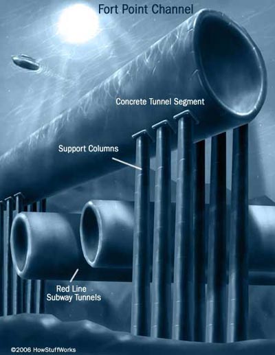
A few miles west, Interstate 90 enters another tunnel that carries the highway below South Boston. Just before the I-90/I-93 interchange, the tunnel encounters the Fort Point Channel, a 400-foot-wide body of water that provided some of the biggest challenges of the Big Dig. Engineers couldn't use the same steel-tube approach they employed on the Ted Williams Tunnel because there wasn't enough room to float the long steel sections under bridges at Summer Street, Congress Street and Northern Avenue. Eventually, they decided to abandon the steel-tube concept altogether and go with concrete tunnel sections, the first use of this technique in the United States.

The problem was fabricating the concrete sections in a way that allowed workers to move into position in the channel. To solve the problem, workers first built an enormous dry dock on the South Boston side of the channel. Known as the casting basin, the dry dock measured 1,000 feet long, 300 feet wide and 60 feet deep -- big enough to construct the six concrete sections that would make up the tunnel. The longest of the six tunnel sections was 414 feet long, the widest 174 feet wide. All were about 27 feet high. The heaviest weighed more than 50,000 tons.

The Fort Point Channel


The completed sections were sealed watertight at either end. Then workers flooded the basin so they could float out the sections and position them over a trench dredged on the bottom of the channel. Unfortunately, another challenge prevented engineers from simply lowering the concrete sections into the trench. That challenge was the Massachusetts Bay Transportation Authority's Red Line subway tunnel, which runs just under the trench. The weight of the massive concrete sections would damage the older subway tunnel if nothing were done to protect it. So engineers decided to prop up the tunnel sections using 110 columns sunk into the bedrock. The columns distribute the weight of the tunnel and protect the Red Line subway, which continues to carry 1,000 passengers a day.

Tunnel-jacking
 Photo courtesy City and County of Denver
The tunnel-jacking process

The Big Dig features other tunneling innovations, as well. For one portion of the tunnel running beneath a railroad yard and bridge, engineers settled on tunnel-jacking, a technique normally used to install underground pipes. Tunnel-jacking involves forcing a huge concrete box through the dirt. The top and bottom of the box support the soil while the earth inside the box was removed. Once it was empty, hydraulic jacks pushed the box against a concrete wall until the entire thing slid forward five feet. Workers then installed spacer tubes in the newly-created gap. By repeating this process over and over, engineers were able to advance the tunnel without disturbing the structures at the surface.

Today, 98 percent of the construction associated with the Big Dig is complete, and the cost is well over $14 billion. But the payoff for Boston commuters should be worth the investment. The old elevated Central Artery had just six lanes and was designed to carry 75,000 vehicles a day. The new underground expressway has eight to ten lanes and will carry about 245,000 vehicles a day by 2010. The result is a normal urban rush hour lasting a couple of hours in the morning and evening.

To see how the Big Dig compares to other tunnel projects, see the table below.

Tunnel
Location
Length
Years to Build
Opened
Cost
Railway Tunnels
Seikan Tunnel
Japan
33.5 mi (53.9 km)
24
1988
$7 billion
Channel Tunnel
England-France
30.6 mi (49.2 km)
7
1994
$21 billion
Apennine Tunnel
Italy
11.5 mi (18.5 km)
14
1934

Hoosac Tunnel
United States
4.75 mi (7.6 km)
22
1873
$21 million
Motor-Traffic Tunnels
Laerdal Tunnel
Norway
15.2 mi (24.5 km)
5
2000
$125 million
St. Gotthard Road Tunnel
Switzerland
10.1 mi (16.2 km)
11
1980

Bridge-Tunnel Complexes
Chesapeake Bay Bridge-tunnel
United States
17.6 mi (28.3 km)
3.5
1964
$200 million
Øresund Bridge and Tunnel
Denmark-Sweden
9.9 mi
(16 km)
8
2000
$3 billion


The Future of Tunneling
As their tools improve, engineers continue to build longer and bigger tunnels. Recently, advanced imaging technology has been available to scan the inside of the earth by computing how sound waves travel through the ground. This new tool provides an accurate snapshot of a tunnel's potential environment, showing rock and soil types, as well as geologic anomalies such as faults and fissures.

While such technology promises to improve tunnel planning, other advances will expedite excavation and ground support. The next generation of tunnel-boring machines will be able to cut 1,600 tons of muck per hour. Engineers are also experimenting with other rock-cutting methods that take advantage of high-pressure water jets, lasers or ultrasonics. And chemical engineers are working on new types of concrete that harden faster because they use resins and other polymers instead of cement.

With new technologies and techniques, tunnels that seemed impossible even 10 years ago suddenly seem doable. One such tunnel is a proposed Transatlantic Tunnel connecting New York with London. The 3,100-mile-long tunnel would house a magnetically-levitated train traveling 5,000 miles per hour. The estimated trip time is 54 minutes -- almost seven hours shorter than an average transatlantic flight.

For lots more information about tunnels and related topics, check out the links on the next page.

Advertisement

Lots More Information

Related HowStuffWorks Articles

More Great Links

Sources

  • Building Big
    http://www.pbs.org/wgbh/buildingbig/
  • Extreme Engineering
    http://dsc.discovery.com/convergence/engineering/archives/archives.html
  • Gundersen, P. Erik. "The Handy Physics Answer Book," Visible Ink Press, Michigan, 1995.
  • Lundhus, Peter. "Bridging Borders in Scandinavia," Scientific American Presents: The Tall, the Deep, the Long, 1999.
  • Macaulay, David. "Building Big: theCompanion to the PBS Series," Walter Lorraine Books, New York, 2000.
  • Massachusetts Turnpike Authority
    http://www.masspike.com/bigdig/index.html
  • Patel, Mukul and Michael Wright, Ed. "How Things Work Today." Crown Publishers, New York, 2000.
  • Sillery, Bob. "Subterranean Giant," Popular Science, June 2002.
    http://www.popsci.com/popsci/automotivetech/
    a0703bcc2eb84010vgnvcm1000004eecbccdrcrd.html
  • "Tunnel Monsters at Work," Popular Science.
    http://www.popsci.com/popsci/technology/generaltechnology/
    0e1877530caf9010vgnvcm1000004eecbccdrcrd.html
  • Vizard, Frank. "The Big Dig," Popular Science, June 2001, pp. 53-57.

Advertisement

Loading...