How Hydraulic Machines Work

Hydraulic machines use fluid to transmit force.
Photo courtesy Caterpillar

­From backyard log splitters to the huge machines you see on construction sites, hydraulic equipment is amazing in its strength ­and agility! On any construction site you see hydraulically operated machinery in the form of bulldozers, backhoes, shovels, loaders, fork lifts and cranes.

Hydraulics operate the control surfaces on any large airplane. You see hydraulics at car service centers lifting the cars so that mechanics can work underneath them, and many elevators are hydraulically operated using the same technique. Even the brakes in your car use hydraulics!

Advertisement

In this ar­ticle, you will learn about the basic principles that hydraulic systems use to do their work, and then we'll examine several different pieces of hydraulic machinery found on a construction site. You will be amazed at the power and versatility available with hydraulics.

­

The Basic Idea

The basic idea behind any hydraulic system is very simple: Force that is applied at one point is transmitted to another point using an incompressible fluid. The fluid is almost always an oil of some sort. The force is almost always multiplied in the process.

For example if two pistons fit into two glass cylinders filled with oil and are connected to one another with an oil-filled pipe. If you apply a downward force to one piston, then the force is transmitted to the second piston through the oil in the pipe. Since oil is incompressible, the efficiency is very good -- almost all of the applied force appears at the second piston. The great thing about hydraulic systems is that the pipe connecting the two cylinders can be any length and shape, allowing it to snake through all sorts of things separating the two pistons. The pipe can also fork, so that one master cylinder can drive more than one slave cylinder if desired.

Advertisement

The neat thing about hydraulic systems is that it is very easy to add force multiplication (or division) to the system. If you have read How a Block and Tackle Works or How Gears Work, then you know that trading force for distance is very common in mechanical systems. In a hydraulic system, all you do is change the size of one piston and cylinder relative to the other.

Hydraulic multiplication. Lets say the piston on the right has a surface area nine times greater than the piston on the left. When force is applied to the left piston, it will move nine units for every one unit that the right piston moves, and the force is multiplied by nine on the right-hand piston.

To determine the multiplication factor, start by looking at the size of the pistons. Assume that the piston on the left is 2 inches in diameter (1-inch radius), while the piston on the right is 6 inches in diameter (3-inch radius). The area of the two pistons is Pi * r2. The area of the left piston is therefore 3.14, while the area of the piston on the right is 28.26. The piston on the right is 9 times larger than the piston on the left. What that means is that any force applied to the left-hand piston will appear 9 times greater on the right-hand piston. So if you apply a 100-pound downward force to the left piston, a 900-pound upward force will appear on the right. The only catch is that you will have to depress the left piston 9 inches to raise the right piston 1 inch.

The brakes in your car are a good example of a basic piston-driven hydraulic system. When you depress the brake pedal in your car, it is pushing on the piston in the brake's master cylinder. Four slave pistons, one at each wheel, actuate to press the brake pads against the brake rotor to stop the car. (Actually, in almost all cars on the road today two master cylinders are driving two slave cylinders each. That way if one of the master cylinders has a problem or springs a leak, you can still stop the car.)

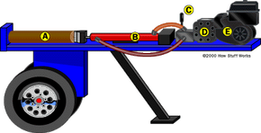
In most other hydraulic systems, hydraulic cylinders and pistons are connected through valves to a pump supplying high-pressure oil. You'll learn about these systems in the following sections.

How Log Splitters Work

The major components of a log splitter are shown here.

The simplest hydraulic device that you find in common use today is the log splitter. It contains all of the basic components of a hydraulic machine:

  • An engine, normally a small four-stroke gasoline engine, provides the power for the system. The engine is attached to a hydraulic oil pump.
  • The hydraulic oil pump creates a stream of high-pressure oil, which runs to a valve.
  • The valve lets the operator actuate the hydraulic cylinder to split a log.
  • There is also a tank to hold the hydraulic oil that feeds the pump and usually a filter to keep the oil clean.

Valves can apply both forward and backward pressure to the piston. One type of valve is a "spool valve" because of its resemblance to a spool from a spool of thread.

Advertisement

Let's look at some of the specifics of these components to see how a real hydraulic system works. If you take a trip down to your local building supply center or a place like Northern Tool and Equipment and look at the log splitters, you will find that a typical backyard log splitter has:

  • A 5-horsepower gasoline engine
  • A two-stage hydraulic oil pump rated at a maximum of 11 gallons per minute (3 gpm at 2,500 psi)
  • A 4-inch-diameter, 24-inch-long hydraulic cylinder
  • A rated splitting force of 20 tons
  • A 3.5-gallon hydraulic oil tank

A two-stage pump is an ingenious time-saver. The pump actually contains two pumping sections and an internal pressure-sensing valve that cuts over between the two. One section of the pump generates the maximum gpm flow rate at a lower pressure. It is used, for example, to draw the piston back out of a log after the log has been split. Drawing the piston back into the cylinder takes very little force and you want it to happen quickly, so you want the highest possible flow rate at low pressure. When pushing the piston into a log, however, you want the highest possible pressure in order to generate the maximum splitting force. The flow rate isn't a big concern, so the pump switches to its "high pressure, lower volume" stage to split the log.

We'll look at hydraulic pumps in the next section.

Hydraulic Pumps

One thing you can see is that the advertised "20-ton splitting force" is generous. A 4-inch piston has an area of 12.56 square inches. If the pump generates a maximum pressure of 3,000 pounds per square inch (psi), the total pressure available is 37,680 pounds, or about 2,320 pounds shy of 20 tons. Oh well...

Another thing you can determine is the cycle time of the piston. To move a 4-inch-diameter piston 24 inches, you need 3.14 * 22 * 24 = 301 cubic inches of oil. A gallon of oil is about 231 cubic inches, so you have to pump almost 1.5 gallons of oil to move the piston 24 inches in one direction. That's a fair amount of oil to pump -- think about that the next time you watch how quickly a hydraulic backhoe or skid/loader is able to move! In our log splitter, the maximum flow rate is 11 gallons per minute. That means that it will take 10 or so seconds to draw the piston back after the log is split, and it may take almost 30 seconds to push the piston through a tough log (because the flow rate is lower at high pressures).

Advertisement

From this discussion you can see that just to fill the cylinder with oil, you need at least 1.5 gallons of hydraulic oil in the system. You can also see that one side of the cylinder has a larger capacity than the other side, because one side has the piston shaft taking up space and the other doesn't. Therefore, big hydraulic machines usually have:

  • Large appetites for hydraulic oil (100 gallons is not uncommon if there are six or eight large hydraulic cylinders used to operate the machine.)
  • Large external reservoirs to hold the difference in the volume of oil displaced by the two sides of any cylinder

Now that you understand the basics of a simple hydraulic system, we can look at some really interesting equipment!

Large Hydraulic Machines

One of the best places to get up close and personal with large hydraulic machines is at a construction site. The thing that is most amazing about these machines is their sheer size. For example, here is a medium-size shovel/excavator:

This machine weighs just over 28 tons, but it can be quite swift in its actions. The bucket can scoop out more than a cubic meter of dirt, which weighs in at approximately 1 to 1.5 tons, and move it around with no difficulty at all. Moving a person around is trivial.

Advertisement

To have this sort of agility, this particular shovel uses an 8.3-liter diesel engine capable of generating 340 horsepower. The engine is connected to a pair of pumps that can generate 140 gallons per minute at 4,500 psi. The hydraulic pistons have 5.5-inch-diameter faces with 4-inch-diameter shafts. In addition, there is one hydraulic motor for each track and a hydraulic motor that can spin the cab and arm at 11 rpm.

You can see from the picture that the arm has a pair of pistons working in unison at the "shoulder" -- one at the "elbow" and then one to rotate the bucket. These pistons, along with the two track motors and the rotating motor, are all controlled by two joy sticks and four pedals in the cab.

These controls send electrical signals to an electrically-operated valve block located next to the pump.

From the valve block, high-pressure hydraulic lines make their way to the cylinders.

Tracks

The tracks are interesting. If you look at the tracks on any piece of large machinery, you will find that there is a hydraulic motor at one end, a free-spinning toothed wheel at the other, and then a set of rollers for the track to move over.

Shovel

Here are the specifications for the Halla HE280LC shovel:

General

  • Weight: 28.2 tons
  • Length: 10.6 meters
  • Width: 3.2 meters
  • Height: 3.3 meters
  • Ground clearance: 0.5 meters
  • Bucket width: 1.3 meters
  • Bucket capacity:1.1 cubic meters

Working range

  • Digging depth: 7.5 meters
  • Vertical digging depth: 5.7 meters
  • Reach: 10 meters

Driving

  • Maximum travel speed: 4.9 km/hr
  • Maximum traction force: 25,143 kgf
  • Swing speed: 11 rpm
  • Maximum digging force: Bucket: 18 tons; Stick: 14 tons
  • Ground pressure: 7.7 psi

Engine

  • Cummins 6CT 8.3-C
  • 8,270 cubic centimeters
  • 340 horsepower at 1,900 rpm

Pump

  • Maximum pressure: 5,000 psi (4,500 psi typical)
  • Oil flow: 2x270 liters per minute

Capacities

  • Fuel: 530 liters
  • Engine oil: 22 liters
  • Hydraulic oil: 320 liters

Skid/Loaders

Another common piece of equipment at any construction site is the skid/loader (also known generically as a "Bobcat" because that was the name given by the manufacturer that first produced them):

Skid/loaders have three pairs of pistons:

Advertisement

  • The first pair raises and lowers the bucket.
  • The second pair rotates the bucket to dump its contents.
  • The third pair splits the bucket so you can use it to grab and pick up things (such as logs).

There are also hydraulic motors on the four wheels.

Dump Trucks

A dump truck isn't much more complicated than the log splitter we saw previously. Dump trucks typically have one cylinder or a pair of cylinders that lift the bed. The only unique thing about these cylinders is that they often telescope, giving them a very long range of motion.

Advertisement

Videos of Hydraulic Machines in Action

These short videos show you three different pieces of hydraulic equipment in operation.

Advertisement

Lots More Information

Related Articles

More Great Links