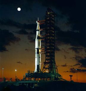
The Apollo 4 spacecraft on top of a Saturn V launch vehicle.
NASA
It was the 1960s, and the space race was on. In 1957, the Soviet Union built and launched Sputnik, the first man-made satellite. The citizens of the United States were shocked -- the idea that another country would beat the U.S. into space was unthinkable. Moreover, if the Soviet Union could launch a satellite into orbit, could it also fire a missile across the world?
The United States government acted quickly to reclaim its reputation as the most scientifically advanced country in the world. To that end, in 1961, President John F. Kennedy addressed Congress about the importance of the United States' role in space. In his speech, Kennedy proposed an ambitious goal: landing a man on the moon before the end of the decade [source: Home of Heroes].
Advertisement
The National Aeronautics and Space Administration (NASA), which was formed in 1958, initiated the Apollo program with the intention of landing a man on the moon. From 1961 to 1972, the Apollo Program's mission was to transport astronauts safely to the moon and then return them to Earth. Remarkably, six of the Apollo missions achieved this goal.
NASA developed the Apollo spacecraft with the help of companies like Boeing, North American Rockwell, McDonnell Douglas, IBM and Grumman. Together, they constructed the complex machinery that could transport a small crew to the moon and back again. What was their creation like, and how did it help NASA fulfill Kennedy's promise?
Before we jump into the mechanics of the spacecraft, let's take a look at the history of the program.
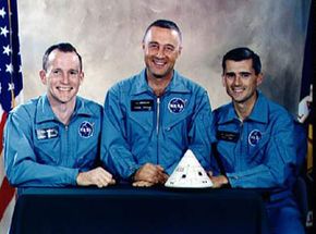
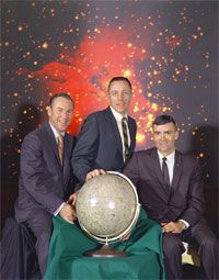
Edward White, Virgil Grissom and Roger Chaffee, the astronauts who died during the Apollo 1 tragedy.
Image courtesy NASA
Over the span of the Apollo program, NASA conducted 33 flights. The earliest flights didn't carry human crews and were meant to test the launch vehicle and the Apollo spacecraft before attempting a lunar mission. NASA officially named 15 of the 33 flights Apollo. Eleven of these Apollo flights were manned. Six of the Apollo missions successfully landed men on the moon and returned them safely to Earth.
Here's a brief overview of the Apollo program:
Advertisement
Missions SA-1 through SA-5: These unmanned missions tested the capabilities of the Saturn I launch vehicle. The Saturn I was a two-stage rocket that used liquid oxygen and kerosene for fuel.
Missions A-101 through A-105: In these tests, a Saturn I launch vehicle carried a mockup of an Apollo spacecraft, called a boilerplate. Instruments in the boilerplate spacecraft measured the stresses astronauts and equipment would experience during a mission.
Missions A-001 through A-004: A series of unmanned flights meant to test Apollo's mission abort procedures, including the launch escape system (LES).
Missions AS-201 through AS-203: Three unmanned missions that tested the Saturn IB launch vehicle and Apollo spacecraft. The Saturn IB was an upgrade from the Saturn I. These flights also tested the propulsion systems onboard the Apollo spacecraft.
Apollo 1, formerly AS-204: On Jan. 27, 1967, three astronauts died in a flash fire inside an Apollo spacecraft during a launchpad test. The test was meant to simulate launch conditions but not actually take off. Later, investigators cited the spacecraft's oxygen-rich environment and exposed wiring as possible causes of the fire. They also pointed out that engineers needed to redesign the spacecraft's exit hatch. NASA renamed the mission Apollo 1 in honor of Roger B. Chaffee, Virgil "Gus" Grissom and Edward H. White, the men who lost their lives in the fire.
Apollo 4 through Apollo 6 (Note: NASA never designated any spacecraft with the name Apollo 2 or Apollo 3): These unmanned missions tested the Saturn V, the launch vehicle designed to propel the Apollo spacecraft into a lunar orbit.
Apollo 7 through Apollo 10: The first manned Apollo missions, these flights tested the spacecraft's performance. Apollo 7 entered an Earth orbit for a few rotations before landing. Apollo 8 was the first manned spacecraft to enter a lunar orbit. During Apollo 9, astronauts tested the lunar module in space for the first time. Apollo 10 tested all of the systems and procedures necessary for a lunar landing, but didn't actually land on the moon.
Apollo 11: Apollo 11 marked the first time a human set foot on the moon. The spacecraft's Lunar Module (LM) landed on the moon's surface on July 20, 1969.
Apollo 12: The second lunar landing tested the spacecraft's ability to make a precise landing on the rocky lunar terrain.
Apollo 13: This mission should have landed astronauts on the moon for the third time, but a malfunction 56 hours into the flight required the astronauts to abort the mission. Two of the spacecraft's oxygen tanks failed, and the Apollo's power system became unreliable. Remarkably, the astronauts onboard worked with mission operatives on Earth to land the spacecraft safely.
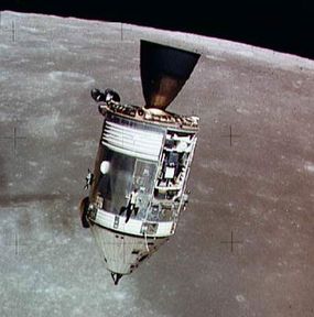
A picture of the Apollo 15 CSM taken from the detached lunar module.
Image courtesy NASA
Apollo 15 through Apollo 17: The final three Apollo missions tested the capabilities of astronauts and equipment in a more extensive stay on the moon's surface. NASA modified the spacecraft to carry an array of sensors and equipment, including a wheeled vehicle called the lunar rover.
Throughout the Apollo program, NASA refined the design of the launch vehicle and spacecraft. Covering every slight modification would require hundreds of pages, so in this article, we'll concentrate on the major systems all of the Apollo spacecraft had in common.
What were all the parts of the Apollo spacecraft? How did they fit together? Keep reading to find out.
An Overview of the Spacecraft
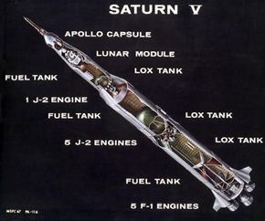
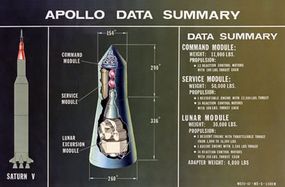
A cross section illustration of the Saturn V and Apollo spacecraft.
Image courtesy NASA
On the launchpad, the combination of the Apollo spacecraft and Saturn V launch vehicle was an imposing sight.
It was more than 400 feet (121.9 meters) tall, and from its base to its top consisted of:
Advertisement
The launch vehicle, which was the three-stage Saturn V rocket in all manned Apollo missions. The Saturn V's job was to launch the Apollo spacecraft into space.
Then there's a structure that looks like a cone with the tip cut off. It was called the spacecraft lunar module adapter (SLA). It protected the lunar module (LM), which couldn't withstand the stress of traveling through the Earth's atmosphere at high speed. The LM was the part of the Apollo spacecraft that actually landed on the moon.
The service module (SM) was next. The service module contained many of the Apollo spacecraft's important systems, including oxygen tanks, fuel cells, batteries and engines. Once the spacecraft separated from the final stage of the Saturn V, the SM provided the thrust needed to adjust the spacecraft's trajectory, pitch, roll and yaw (the rotation about the three axes of the spacecraft).
Above the SM was the command module (CM), where the astronauts sat for most of the mission. The CM contained the array of controls and displays the astronauts used to monitor the spacecraft's integrity and performance. Many of Apollo's functions were automatic, but astronauts had to initiate some of them and could choose to switch other functions to manual control if necessary. The CM also had many of the same systems that the SM had, both to act as a backup and to control the spacecraft's entry into the Earth's atmosphere at the end of a mission.
Finally, on top of the CM was the launch escape system (LES). It was a tower-shaped structure that looked like a small rocket on top of a trellis. The purpose of the LES was to provide the astronauts a quick means of escape in case of a launch failure. In such a situation, the LES would pull the CM away from the launch vehicle using three solid propellant rocket engines.
In contrast, when the Apollo spacecraft re-entered the Earth's atmosphere and landed in the ocean, it was just shy of 11 feet tall. That's because NASA intended for only the command module to return to Earth in one piece -- everything else was jettisoned either over the Atlantic Ocean or into space.
The cost of the program was estimated at more than $25 billion, which would be more than $100 billion today when adjusted for inflation [source: NASA]. Most of that money was spent designing, building and refining the complex systems and machinery required to transport men to and from the moon safely. NASA allocated the rest of the budget for astronaut training, ground control systems and related expenses.
Now that we've got an overview, let's take a closer look at each of these components. We'll start with the Saturn V launch vehicle in the next section.
The Apollo Launch Vehicle
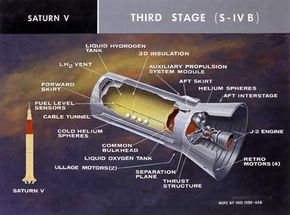
A cross section of the S-IVB section of the Saturn V rocket.
Image courtesy NASA
The Saturn V launch vehicle packed a lot of power into its three-stage structure. The rocket consisted of three sections bolted together: The base section was stage I, above which was stage II and on top of which was stage III. At the very top of the rocket sat the Saturn V's instrument panel and control system, which automatically guided the sequence of ignitions required to launch the Apollo spacecraft into orbit.
Let's look at each of these sections in turn:
Advertisement
Stage I was called the S-IC. It had five rocket engines that used liquid oxygen and kerosene as fuel. Each engine produced 1.5 million pounds (6,675,000 newtons) of thrust. Together, the engines could generate 7.5 million pounds (33,375,000 newtons) of thrust. Think of thrust as the strength of a rocket engine. This thrust pushed the entire vehicle assembly more than 36 miles (57.9 km) vertically at a speed of 9,030 feet (2,752 m) per second (fps). At that point, the S-IC's engines shut off. Explosive bolts connecting S-IC to the rest of the Saturn V vehicle detonated, jettisoning stage I into the Atlantic Ocean.
Stage II (S-II) had five J-2 engines that together could produce 1,125,000 pounds (5,006,250 newtons) of thrust. In this stage, the Saturn V accelerated to a speed of 22,746 fps (6,932 meters per second). The S-II carried the rest of the vehicle up to an altitude of 101 miles (162.5 kilometers) before shutting off. Like the S-IC, the S-II then separated from the rest of the vehicle by igniting the explosive bolts connecting it.
Stage III was called the S-IVB, which NASA previously used on the Saturn IB launch vehicle. This final stage had a single J-2 rocket engine that could provide 225,000 pounds (1,001,250 newtons) of thrust. It was this stage of the Saturn V rocket that put the Apollo spacecraft into Earth's orbit. Once in orbit, the engines powered down temporarily. When the spacecraft achieved the proper alignment after a few rotations around the Earth, the engines would reignite. The resulting thrust guided the Apollo spacecraft into a lunar trajectory. After this second ignition, the S-IVB separated from the spacecraft. The S-IVB also housed the Saturn V's instrument panel at the far forward end (the "top" of the Saturn V).
The instrument panel included guidance and navigation systems, measuring devices, power supplies and telemetry transmitters. Telemetry refers to technology that can gather data and transmit it to another location automatically. In this case, the information gathered included velocity and spacecraft orientation, and the instruments transmitted the data to crews on the Earth.
While launches were impressive to watch and relied on a complex series of controlled ignitions, they were just the tip of the iceberg for the Apollo missions. Where were the astronauts during the launch, and from where did they control the spacecraft? Find out in the next section.
The Apollo Command and Service Modules
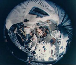
A fish-eye view of a lunar module simulator. Looks cozy, doesn't it?
Image courtesy NASA
After the launch, the spacecraft jettisoned not only stages I and II of the Saturn V launch vehicle, but also the launch escape system (LES). Once the S-IVB inserted the spacecraft into a lunar trajectory, it separated from the rest of the vehicle. At that point, the spacecraft would jettison the 4,000 pound spacecraft lunar module adapter (SLA). Now, all that remained of the spacecraft was the command module (CM), the service module (SM) and the lunar module (LM).
The command module was where the astronauts spent almost all of their time and was the only section of the spacecraft designed to return to Earth intact. With its heat shield, it was 12 feet, 10 inches tall (about 3.9 m) and weighed 12,250 pounds (5.5 metric tons). Inside, the astronauts had about 210 cubic feet (64 m) of habitable space -- the rest of the space inside the vehicle was dedicated to control panels and displays. The CM held a crew of three astronauts. At launch, the three men would sit on a couch that they could later fold and stow away when they entered space.
Advertisement
Engineers built the CM using sheet aluminum for the inner structure. On the outside of the CM was a heat shield of brazed stainless steel coated with resin. Without the heat shield, the astronauts would not have survived re-entry into the Earth's atmosphere at the end of the mission.
The service module was a 24.6 foot (7.5 meters) tall cylinder. It was 12.8 feet (3.9 meters) wide and weighed a whopping 51,243 pounds (23,243.4 kilograms) at launch. The SM had six sections inside, which contained a propulsion system, tanks for fuel and oxidizer material, helium tanks used to pressurize the fuel system, fuel cells and tanks of oxygen and hydrogen. The fuel cells provided the power for most of the crew's needs during the mission, but both the SM and CM also carried batteries to supplement power.
For most of the mission's flight, the CM and SM remained connected together. The CM relied on the SM's systems for most of its operations. Because of this, some people refer to the two units as a single entity: The CSM.
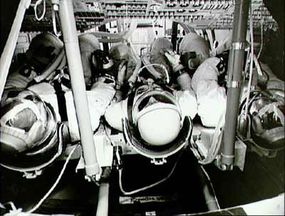
There wasn't much elbow room in the Apollo command module during takeoff and landing.
Image courtesy NASA
The top of the CSM contained a probe mechanism the astronauts used to dock with the LM. Once the spacecraft lunar module adapter separated from the rest of the vehicle, the Apollo spacecraft detached the LM from its base. Using reaction control engines (RCEs), the CSM adjusted its alignment so that the top of the CM faced a funnel-shaped device in the LM called a drogue. The astronauts in the CSM would align the probe so that it docked with the LM's drogue. Once docked, 12 automatic latches secured the LM to the top of the CM. In other words, the LM moved from behind the CSM to the front of it. Astronauts could remove the probe and drogue assemblies from inside the spacecraft, allowing the crew to move between the two modules.
To make space travel possible -- and safe -- the CSM had to integrate several complex support systems. Keep reading to learn how astronauts could accomplish their missions by relying on these systems.
CSM Systems and Controls
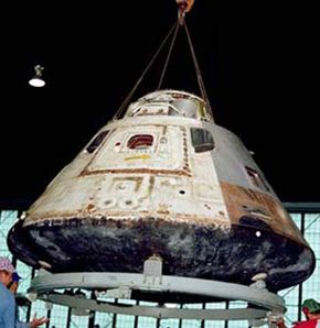
An Apollo command module on display
Image courtesy NASA
The systems aboard the CSM fulfilled a range of functions, including navigation, guidance, communication, life support, electrical power, water management and propulsion.
Here's a quick breakdown on the systems in the CSM:
Advertisement
Electrical power system (EPS): The EPS consisted of fuel cells and batteries and provided both direct and alternating current electricity. Most of the EPS's systems were in the SM, but the CM carried three batteries.
Guidance, navigation and control system (GNCS): The purpose of this system was to measure and control the spacecraft's position, attitude and velocity. The GNCS included inertial, optical and computer subsystems. The inertial subsystem used accelerometers to measure the spacecraft's speed and rotation along its three axes. The optical system included a telescope, a sextant and an electronic system that sent optical data to the spacecraft's computer for navigation purposes. The computer system analyzed data from the other subsystems as well as from manual commands from astronauts. Then the computer would send the commands to the spacecraft's propulsion system to make course adjustments. The computer also had a digital autopilot that could control the spacecraft during all phases of the mission.
Stabilization and control system (SCS): This system included controls and displays for the crew of the Apollo to adjust the spacecraft's rotation or velocity manually. The system sent commands to the spacecraft's propulsion system.
Service propulsion system: Located in the SM, this propulsion system included four tanks of hydrazine fuel and nitrogen tetroxide oxidizer. These substances are hypergolic, which means they ignite spontaneously when mixed together. The system used helium tanks to pressurize the fuel lines. The system's rocket engine produced up to 20,500 pounds (91,225 Newtons) of thrust. NASA mounted the engine on a gimbal, which is a support that can pivot. By pivoting the engine in the right direction, the spacecraft could maneuver to the right attitude and trajectory.
A cutaway illustration of the Apollo spacecraft, including the lunar module.
Image courtesy NASA
Reaction control systems (RCS): The RCS was a system of engines and fuel tanks. It was partly used as a redundant system, meaning it could control the spacecraft's movement if the main propulsion system went offline. Both the CM and SM had an independent RCS. The SM had four quads, which were groups of four rocket engines. Each engine could supply 100 pounds (445 newtons) of thrust. The CM had two six-engine groups, with each engine capable of supplying 93 pounds (413.9 newtons) of thrust. The CM's RCS also provided spacecraft control during re-entry.
Telecommunication system: This system provided intercommunication between the astronauts in space and staff back on Earth as well as between the astronauts themselves. It included S-band and very high frequency (VHF) radio transmitters and receivers and a transponder. Astronauts used the VHF equipment for short-range communication and the S-band equipment to communicate across deep space. Whenever a large body -- for example, the moon -- was between the spacecraft and the flight crew on the ground, communication was lost.
Environmental control system (ECS): This system controlled the spacecraft's atmospheric pressure and temperature and also managed water. It collected water from the ship's fuel cells (a useful byproduct). The ECS adjusted the temperature in the CSM through a water and glycol cooling system. The system pumped the water and glycol through coolant loops to reduce the temperature of the liquid. Then the system pumped the liquid through tubes to cool the CSM's atmosphere and electric systems, much like a liquid-cooled computer's cooling system.
Earth landing system: Housed in the CM, this system consisted of several mortar-deployed parachutes. NASA designed the Apollo spacecraft with the intention of a water landing upon re-entry. The parachutes slowed the spacecraft's descent enough to ensure the safety of the crew inside the spacecraft.
Think that's a lot of information? The list above just scratches the surface of the CSM's systems and controls, and we haven't even looked at the lunar module yet. Read on to find out how that feat of engineering worked.
I Need More Power, Captain!
The crew of Apollo 13 never made it to the moon's surface, but they made good use of the LM. When the CSM's power failed, they tapped into the LM's power supply, which gave them just enough power to plot a return course to Earth.
The Lunar Module
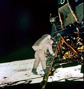
An astronaut climbs down the lunar module's ladder to the moon's surface.
Image courtesy NASA
Apollo's lunar module (LM) was the first manned vehicle designed to operate completely outside the Earth's environment. It remained docked with the CSM during Apollo's journey into a lunar orbit. Once in orbit, two of the three-man crew transferred from the CSM to the LM. After sealing both the CSM and LM, the astronauts separated the two vehicles and the LM began its journey down to the surface of the moon.
The LM had two sections. The upper section was the ascent stage. This section contained the crew compartment, system displays and controls, S-band and radar antennae, a reaction control system (RCS), fuel and oxidizer tanks and oxygen tanks. The lower section was the descent stage. It stored equipment the astronauts would use on the moon. It also had a descent rocket engine, landing gear and fuel and oxidizer tanks. Both sections made the descent down to the moon, with the descent section controlling the landing. But when the astronauts left the moon, it was only in the ascent section. The descent section served as a launchpad and was left behind.
Advertisement
The LM had landing radar that transmitted beams of microwaves to the lunar surface and then measured the waves that the surface reflected back toward the spacecraft. By calculating the delay between transmission and reception and measuring the waves, the LM's computer could calculate the module's proximity to the surface and make adjustments.
After landing on the moon, the two crew members would prepare first the ascent stage of the LM for liftoff. Then, they'd rest and prepare for their mission objectives on the moon's surface. Once they had completed those objectives, they'd return to the LM for ascent. The upper section of the LM would separate from the descent stage (once again using explosive bolts). The ascent stage's RCS provided 3,500 pounds of thrust, enough to launch it into lunar orbit.
NASA designed the ascent stage's radar antenna to receive transmissions from the transponder in the CSM. The transponder transmitted information regarding the CSM's position and velocity. With this information, the two sections maneuvered so that they could dock together. After docking, the crew from the LM transferred over any sample materials they gathered on the moon. Then they sealed off both vehicles and jettisoned the LM, sending it on a collision course with the moon. Instruments left on the moon's surface measured the impact as part of a seismic research project.
At this stage in the mission, all that was left of the Apollo spacecraft was the CSM. How did the astronauts pilot back to Earth, and what was re-entry like? Keep reading to find out.
The Lunar Thermos
NASA experimented with several designs while trying to determine the best way to maintain the temperature inside the LM. Rather than incorporate a heavy environmental control system like the one in the CSM, NASA decided to insulate the LM so that it acted like a giant thermos. It worked like a charm -- the LM's average temperature varied between 65 and 70 degrees Fahrenheit (between 18.3 and 21.1 degrees Celsius) during lunar operations.
Apollo's Re-entry
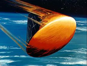
An artist's rendering of the Apollo command module's re-entry into the Earth's atmosphere.
Image courtesy NASA
After jettisoning the LM, the Apollo spacecraft was ready to return home. NASA used the SM's propulsion system to insert the spacecraft into a transearth injection (TEI), which means Apollo would be heading back to Earth in a trajectory that allowed for a controlled descent into the Pacific Ocean.
To prepare for the return trip, the astronauts had to retrieve the launch couch and reinstall it for landing. Just before re-entry into the Earth's atmosphere, the astronauts jettisoned the service module from the command module. The CM then adjusted its attitude -- or orientation respective to the Earth's surface -- using its thrusters so that the base of the module faced towards the Earth's surface.
Advertisement
The temperature on the CM's surface climbed up to 5,000 degrees Fahrenheit, but the heat shields protected the inner structure of the CM. The heat shield was ablative, which means that it was designed to melt and erode away from the CM as it heated up. From the ground, it would look as if the CM had caught on fire during its descent. In reality, the ablative covering is what kept the astronauts inside the CM safe -- the material diverted heat away as it vaporized.
The atmosphere acted like a braking system on the spacecraft. To further slow the CM's descent, the spacecraft used mortar-deployed parachutes. The Apollo spacecraft had three large parachutes and could safely land with only two deployed. Eventually, the CM splashed down into the Pacific Ocean. The top of the CM housed several balloons and air compressors. If the CM landed upside down in the ocean, the astronauts could activate the balloons in an attempt to turn the spacecraft upright.
Once safe in the ocean, the spacecraft's ventilation system allowed fresh air into the capsule. The astronauts used VHF recovery beacon and radios to guide a recovery ship to the spacecraft's location. A ship recovered the crew and capsule.
The information gathered by the astronauts during the Apollo missions has become invaluable to NASA and scientific knowledge in general. In the future, NASA hopes not only to return to the moon, but also build a lunar station where people can study the moon during extensive stays.
To learn more about the space program and related topics, take a little moonwalk to the links on the next page.
The Men on the Moon
Six of the manned Apollo missions successfully landed on the moon and returned to Earth. So far, those landings mark the only times that human beings have walked on the moon's surface. Only two out of the three astronauts on each mission had the chance to touch down on the moon (the third had to stay with the CSM in lunar orbit). Here are the dozen astronauts who have walked on lunar soil: